
Mould Flow Analysis: Catch Plastic Part Defects Before You Cut Steel
A beginner-friendly guide to mould flow analysis in NX and Autodesk — fill, pack, cooling and warpage simulation, gate location, and how it saves costly tooling rework.
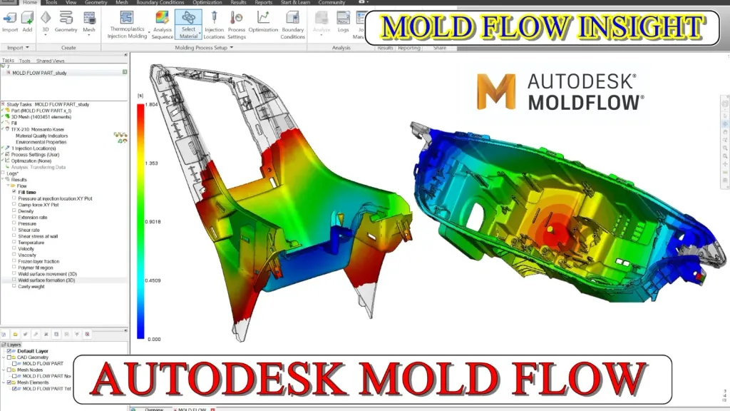
Cutting a mould is expensive, and reworking one is worse. Mould flow analysis (also called injection-moulding simulation) lets you predict how plastic will behave inside your tool — before a single block of steel is machined. It’s one of the highest-leverage skills a mould designer can add.
Why simulate at all?
Plastic doesn’t fill a cavity the way intuition suggests. Flow front behaviour, pressure, temperature and cooling all interact to create defects that are invisible on the CAD model. Simulation turns those invisible risks into visible, fixable results — saving weeks of tooling trials and thousands in rework.
What the analysis actually predicts
A complete flow study answers the questions that decide part quality:
- Fill analysis — will the part fill completely, or short-shot? Where does the flow front end?
- Weld and meld lines — where flow fronts meet, creating cosmetic and strength weaknesses.
- Air traps — trapped gas causing burns or incomplete fill.
- Pack and hold — sink marks and dimensional stability.
- Cooling — hot spots that lengthen cycle time and cause warpage.
- Warpage — how the finished part will distort after ejection.
Gate location changes everything
The single most influential decision in flow analysis is gate location. Move the gate and you change the fill pattern, weld-line position, pressure requirement and warpage. Learning to test gate options in simulation — instead of guessing — is what makes your moulds fill cleanly and eject flat.
From results to design decisions
Simulation is only useful if you act on it. The workflow is a loop:
- Build a sensible mesh from the part.
- Set material, injection location and process conditions.
- Run fill, pack and cooling analyses.
- Read the results and identify the risk.
- Change the gate, wall thickness, or cooling layout — and re-run.
Each iteration is cheap in CAD and priceless compared to modifying a finished tool.
How it makes you a better mould designer
Designers who understand flow think differently: they place gates deliberately, avoid thin-to-thick transitions, and design cooling for uniformity from the start. Even a working knowledge of mould flow analysis dramatically reduces the defects that show up on the shop floor — which is exactly why simulation skills command a premium.
Getting started
You don’t need to be a simulation specialist to benefit. Learn the core analyses — fill, pack, cool, warp — and practise reading their results on real parts. Pair that with your mould design skills, and you’ll design tools that work the first time, not the third.
Frequently asked questions
- What is mould flow analysis used for?
- It simulates how molten plastic fills, packs and cools inside a mould so you can predict defects — short shots, weld lines, air traps, sink marks and warpage — and fix them in CAD before machining the tool.
- Do I need to be a mould designer to learn flow analysis?
- It helps, but the course is structured so design and simulation reinforce each other. Understanding flow analysis actually makes you a better mould designer.
- Which software does the course use?
- It covers mould flow analysis across NX and Autodesk tools, so you learn the concepts and can apply them in the simulation environment your company uses.