
Plastic Injection Mould Design in NX: From Part to Production-Ready Tool
How to learn plastic injection mould design in Siemens NX — core and cavity extraction, mould base, feeding, cooling, ejection, and slider & lifter mechanisms explained with a real workflow.
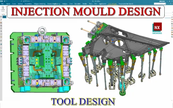
Plastic injection mould design is the backbone of mass-produced plastic — from helmet shells and visors to automobile trim and preforms. It is also one of the highest-value CAD skills you can build, because a mould designer’s decisions directly determine part quality, cycle time and tool cost. Here is how to learn it the way industry actually practises it.
Understand the mould before you model it
An injection mould is a system: molten plastic is injected, packed, cooled and then ejected — thousands of times. Every design choice serves that cycle. Before extracting core and cavity, you should be able to read a plastic part and predict its parting line, draft, undercuts and likely defects. This “design intent first” habit is what separates good mould designers from CAD operators.
Core and cavity extraction is the heart of the job
The single most important skill is splitting a part into core and cavity. That means:
- Building clean parting lines and parting surfaces, including split-type surfaces for complex geometry.
- Handling automobile parts with patched, multi-surface parting — the hardest and most in-demand case.
- Extracting solid cores confidently, even when the part fights you.
Practising this across many parts — switch boards, phone housings, saw covers, car grills and door trims — is the fastest way to build real intuition.
Build the mould base and feeding system
Once you have core and cavity, you assemble the tool:
- Mould base design in assembly mode, and with expressions/DME standards.
- Guide pillars and bushes, tolerances and plate materials.
- Feeding system — sprue, runner and gate design (edge, fan, pin-point, submarine, spoke), with calculations.
- Cooling channels sized for even heat extraction and shorter cycle time.
- Ejection — ejector pins, stripper plates and spring design.
Master the mechanisms that pay the bills
Straightforward moulds are easy; the money is in mechanisms. Learn:
- Sliders and lifters, including double lifters and reverse sliders.
- Collapsible cores for internal undercuts.
- Unscrewing / gear moulds (rack-and-pinion and motor types) for threaded parts.
- Three-plate and family moulds, thin-wall and IML tooling, preform moulds.
Every one of these has a calculation and a mechanism you can only learn by building it on a real part.
Finish like a professional
Production tooling needs more than geometry: electrode design, in-house quotation, BOM preparation and mould animations to validate motion. These “last mile” skills make you immediately useful in a design office.
Your learning plan
Work one complete mould from part to finished tool before moving to the next. Keep every project file — visor moulds, automobile parts, slider-and-lifter tools — as a portfolio. When you can hand over a fully detailed, mechanism-complete mould with feeding and cooling, you are ready for a mould design role.
Frequently asked questions
- Is Siemens NX good for injection mould design?
- Yes. NX is used across the automotive and appliance mould industry for its powerful parting, Mould Wizard, and surfacing tools. Skills transfer well to other platforms once you understand the design logic.
- How long does it take to become a mould designer?
- With consistent practice on real parts, most learners reach an employable level in a few months. The key is completing full mould designs end to end, not just watching lectures.
- What are the hardest parts of mould design to learn?
- Complex parting surfaces on automobile parts, and mechanisms like sliders, lifters, collapsible cores and unscrewing devices. These are exactly the areas real courses spend the most case studies on.