
Plastic Mould Design in SolidWorks: A Practical Path for Beginners
Learn plastic mould design in SolidWorks — parting lines, core and cavity, mould tooling, side cores and a production workflow that gets you job-ready.
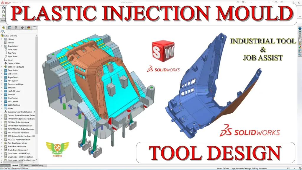
SolidWorks is one of the most widely used CAD platforms in industry, and its Mold Tools make it an excellent place to learn plastic mould design. If you want to design injection moulds without a steep software curve, this is a practical, job-focused path. Here’s how to approach it.
The mould-design mindset
A mould is a negative of the part, split so it can open and eject. Before touching any tool, learn to look at a plastic component and see its parting line, draft, undercuts and likely gate. This “read the part first” habit matters more than any single command and carries across every CAD package.
SolidWorks Mold Tools, step by step
SolidWorks gives you a guided sequence that mirrors real mould-making:
- Draft analysis — confirm the part can release from the tool.
- Scale/shrinkage — compensate for plastic shrink so the part comes out to size.
- Parting lines — define where core and cavity separate.
- Shut-off surfaces — close through-holes so the split works.
- Parting surfaces — build the surface that divides the mould halves.
- Tooling split — generate the core and cavity blocks.
- Core — create side cores for undercuts.
Practising this workflow on progressively harder parts is what makes it stick.
Handle undercuts with side cores
Simple parts split cleanly; real ones rarely do. Undercuts — snaps, side holes, hooks — require side cores and lifters. Learning to identify an undercut and design the mechanism to release it is the difference between a textbook mould and a manufacturable one.
Build toward complete tools
Beyond core and cavity, a production mould needs a mould base, feeding, cooling and ejection. Even as you learn in SolidWorks, keep the whole tool in mind: where the gate feeds, how the part cools evenly, and how it ejects without damage. Designing with the full system in view is what employers look for.
Practise on real parts and keep a portfolio
The fastest way to get hired is to show finished work. Rebuild each course part yourself, document your parting and mechanism decisions, and keep the files. A folder of completed mould designs — with core, cavity and side cores — speaks louder than any certificate.
Where SolidWorks fits in your career
SolidWorks mould skills are directly employable and a superb foundation. Once the parting-and-tooling logic is second nature, moving to NX, Mould Wizard or advanced automobile moulds becomes far easier, because you’re learning a new tool — not a new concept. Start here, build real moulds, and grow from there.
Frequently asked questions
- Is SolidWorks good for plastic mould design?
- Yes. SolidWorks has a dedicated Mold Tools workflow — draft analysis, parting lines, shut-off surfaces, parting surfaces, tooling split and core creation — that makes it a strong, accessible platform for mould design.
- Do I need to know SolidWorks modelling first?
- Comfortable part modelling helps, but the course builds mould-specific skills step by step on real parts, so dedicated beginners can follow with practice.
- Can SolidWorks mould skills transfer to NX or other software?
- The design logic — parting, core/cavity, tooling, mechanisms — is universal. Learning it in SolidWorks transfers directly when you move to NX or other CAD platforms.